
-
Home

-
Other instructions
-
Replacing Laser Scanner Assemblies HP LaserJet printers
- Replacing the Laser Scanner Assembly HP LaserJet P3015 P3015n P3015dn P3015x
Replacing the Laser Scanner Assembly HP LaserJet P3015 P3015n P3015dn P3015x
 The laser scanner assembly is a fairly common part to fail on the HP LaserJet P3015 family of printers. If you are seeing repeated error codes of 51.10 or similar, you should replace the laser scanner. Instructions for replacing this assembly begin below.
How to Replace the Laser Scanner Assembly HP LaserJet P3015 P3015n P3015dn P3015x
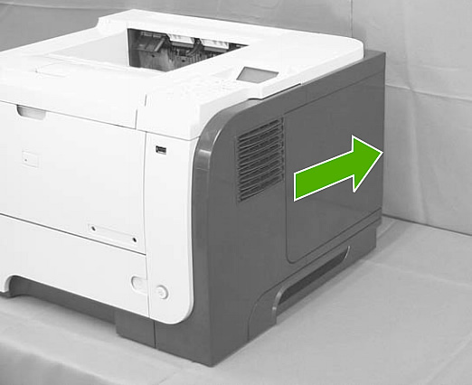
1. Slide the DIMM cover (on the right side of the printer) toward the back of the printer.
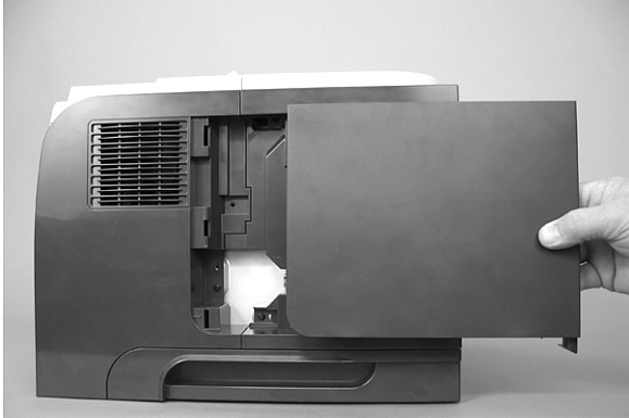
2. Remove the DIMM cover.
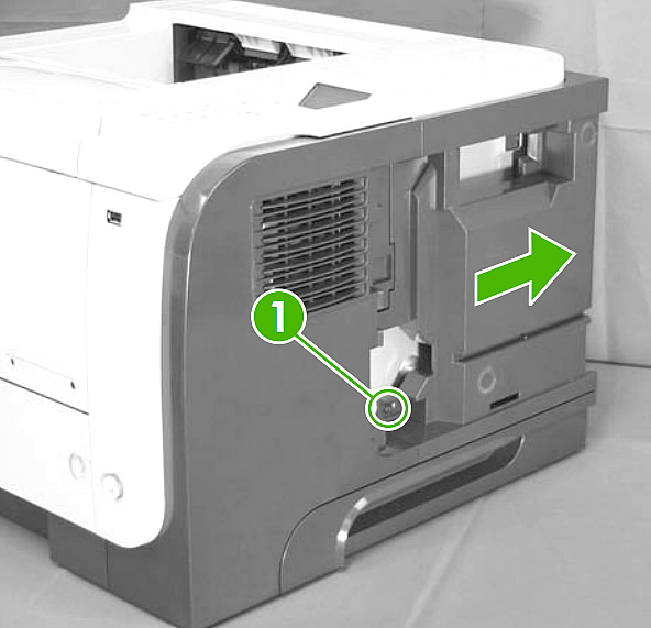
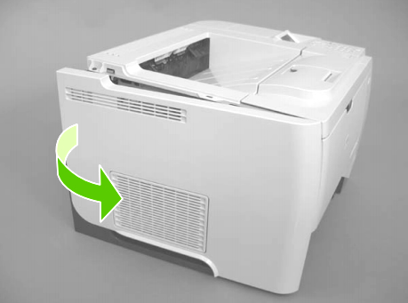
3. Next, remove 1 screw and slide the formatter cover towards the back of the printer. (see picture below)
4. Remove the formatter cover from the printer.
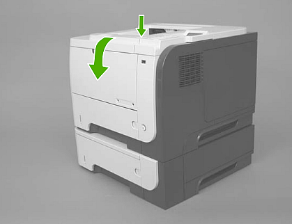
5. Open the rear door.
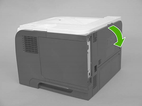
6. Gently pull down on the door and lower the door until it is fully open.
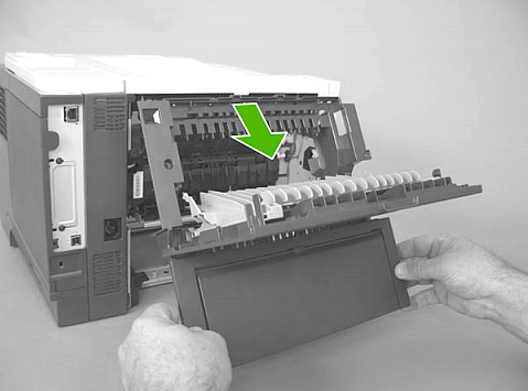
7. Push up on the link arm to release it. The link arm is under spring tension-- do not let the link arm snap back toward the printer when you release it.
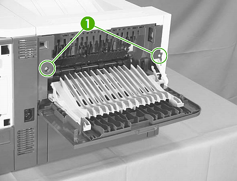
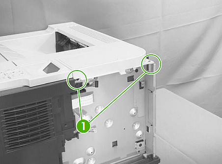
8. Remove two screws (circled as callout 1 in the picture below).
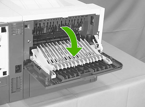
9. Open the lower-rear door, and then release a tab on the lower right hand side as you face the rear (circled in picture below).
10. On the opposite side (lower left hand side as you face the rear), release another tab as circled in picture below.
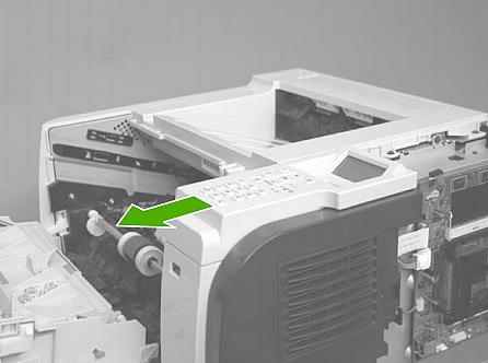
11. Rotate the bottom of the rear-door assembly away from the printer.
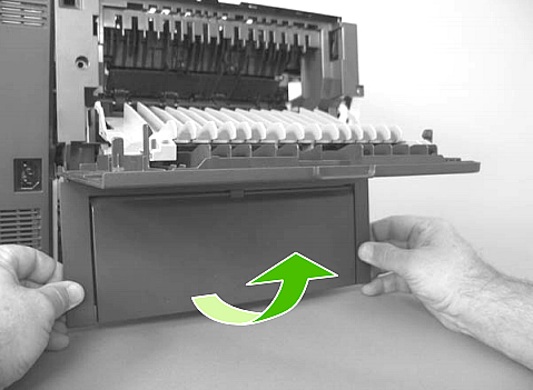
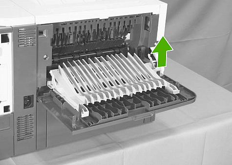
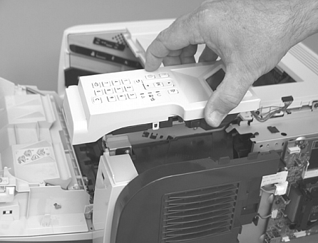
12. Pull down on the rear-door assembly to remove it.
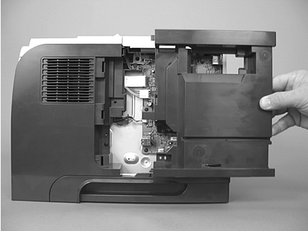
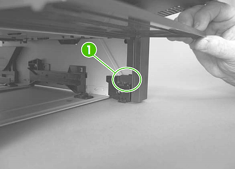
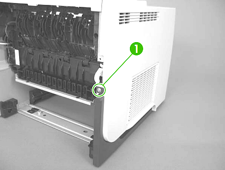
13. Accessing from the rear, remove the screw which is securing the left side cover (see picture below).
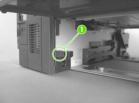
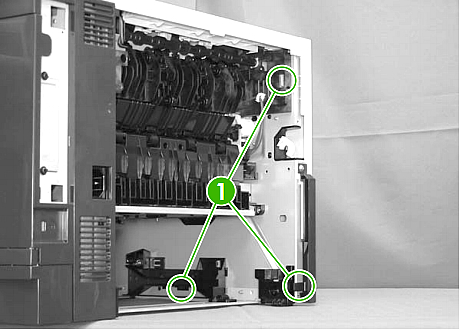
14. Next, accessing from the rear, release 3 tabs which are securing the left side cover in place. See picture below.
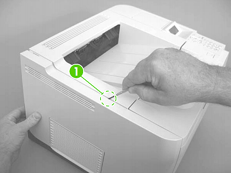
15. Release one tab located at the top of the left side cover, approximately in the center, see picture below.
16. Next, rotate the rear of the left cover slightly away from the printer, and then slide the cover towards the front of the printer to remove it.
17. Remove 2 screws from the top right cover, circled in picture below.
18. Next, lift the top right cover off the printer to remove it.
19. Press the release button and open the front cartridge door. Make sure it is completely open.
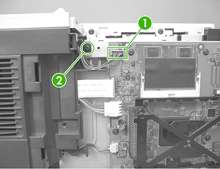
20. Disconnect the control panel's cable (circled as callout 1 in picture below), and remove 1 screw (circled as callout 2 in picture below).
21. Slide the control panel toward the front of the printer to release it.
22. Lift the control panel off the printer.
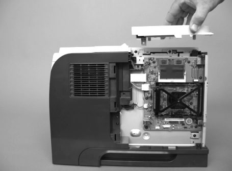
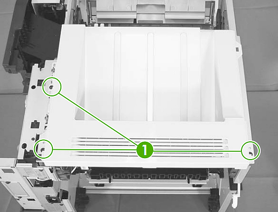
23. Remove three screws from the top cover assembly.
24. Slightly lift the rear of the cover, slide the cover toward the front of the printer, and then remove it.
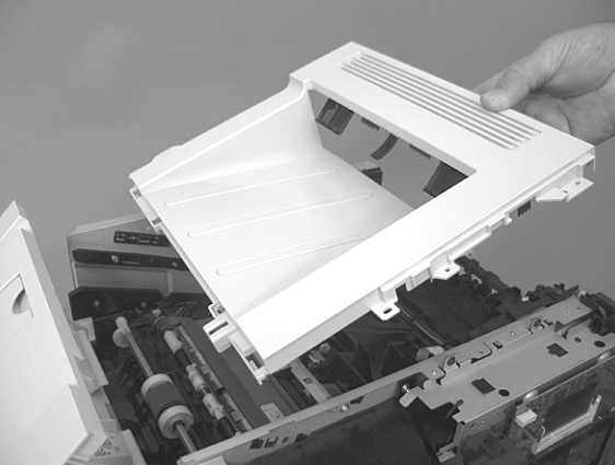
25. Release 1 tab (circled as callout 1 in picture below) on the air duct, and then lift the air duct (labeled callout 2 in picture below) out of the printer.
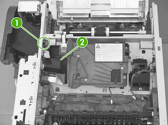
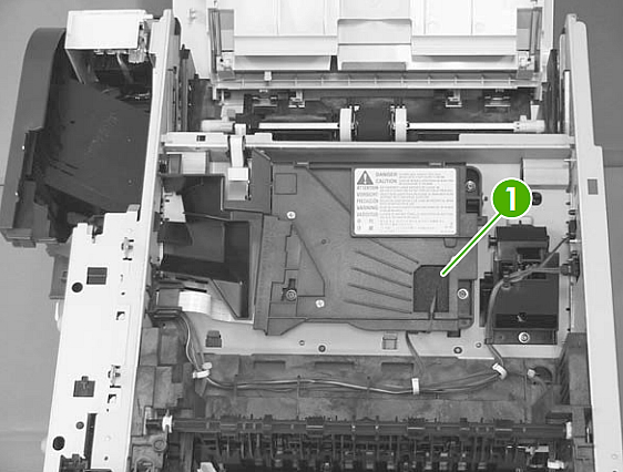
26. Remove the antistatic sponge which covers the standard cable -- see picture below.
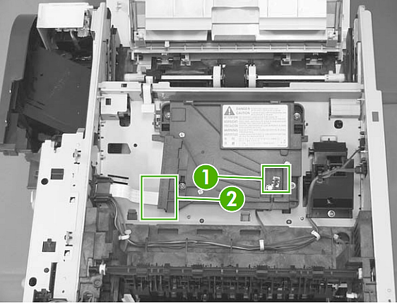
27. Disconnect the standard cable (callout 1 in picture below) and the ribbon cable (callout 2 in picture below).
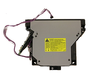
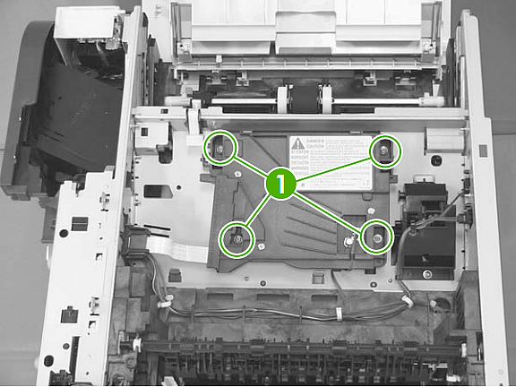
28. Remove 4 screws from the top of the laser scanner assembly, see photo below.
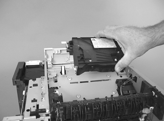
29. Lift the laser scanner assembly up and out of the printer.
30. Install new laser scanner assembly, and re-attach 4 screws.
31. Replug the standard cable and the flat ribbon cable. Transfer the antistatic sponge to the new laser scanner and install it over the standard cable plug. Re-install the air duct.
32. Finish by reassembling panels in reverse order of the previous steps.
Tech Support
Featured Articles