-
Home

-
Other instructions
-
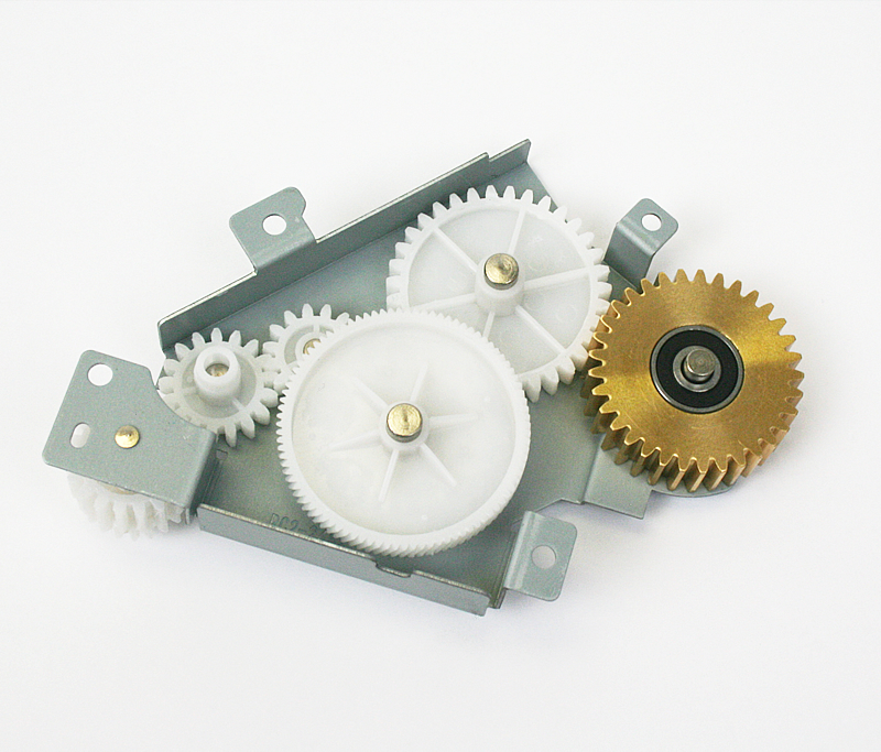
Replacing Fuser Drive Gears HP LaserJet P4015 series
- Step 1: Removing the Covers LaserJet P4014 P4015
Removing the Covers , HP LaserJet P4015

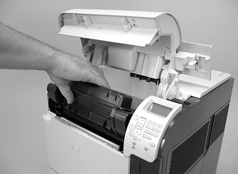
Step 1 in replacing the fuser drive gears on an HP LaserJet P4014, P4015, or P4515 is to remove the covers & panels.
Remove the toner cartridge as shown in picture below.
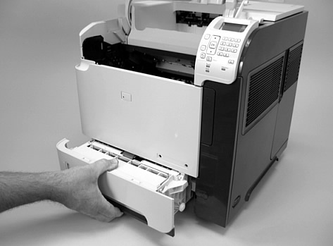
Remove Tray 2 as shown below.
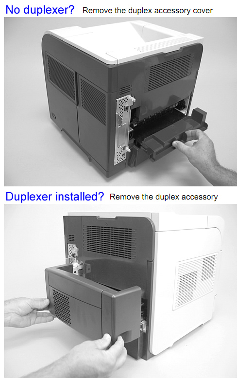
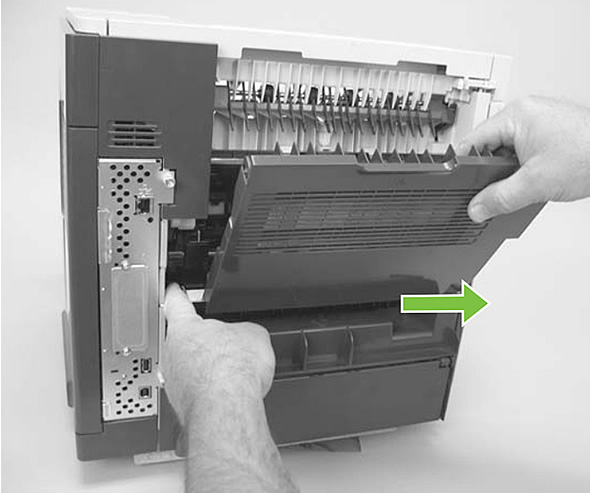
Remove the duplex cover, or remove the duplex accessory if you have it installed, from the back of the printer. See 2 pictures below of duplex cover and duplex accessory.
Remove the Formatter Cover and Formatter
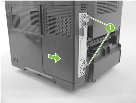
Remove the plastic formatter cover by sliding it towards the back of the printer; then loosen the two thumb screws on the formatter, as shown in picture below.
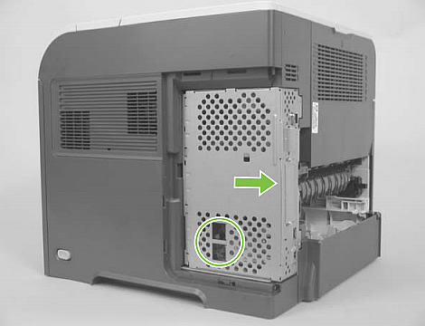
Remove the formatter by sliding it towards the back of the printer, see picture below.
Remove the Top Cover
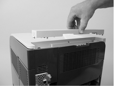
Remove the Top Accessory Cover, see picture below.
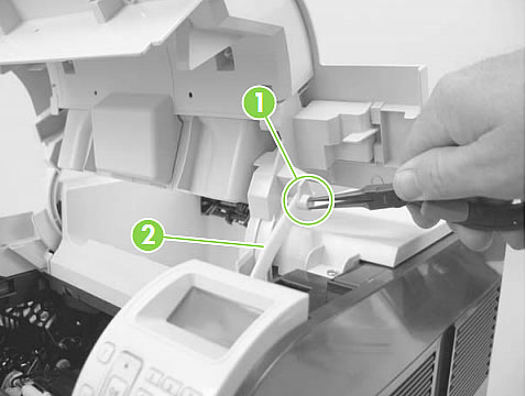
Open the toner access door, and use needle-nose pliers to release the tab which attaches the print-cartridge drive arm to the door. See callout 1 in the picture below. Once that tab is released and the arm is free, push the arm (callout 2 in picture below) back down into the printer so it won't catch or get damaged when you remove the top cover.
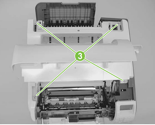
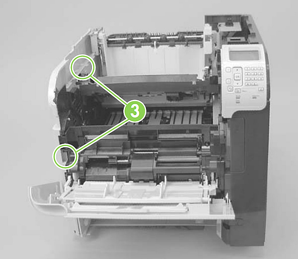
To remove the top cover, there are 4 screws to remove, 2 at the front and 2 at the back. See the location of the 4 screws in picture below (labeled callout 3).
Partially close the toner access door, and then use a small flat blade screwdriver to release 2 tabs on the top cover, see callout 4 in picture below.
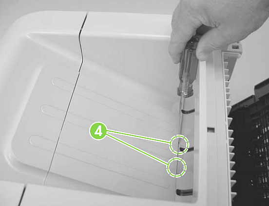
NOTE: Later, when you are reassembling the printer, watch out for these tabs and make sure they get fully seated as you reinstall the top cover.
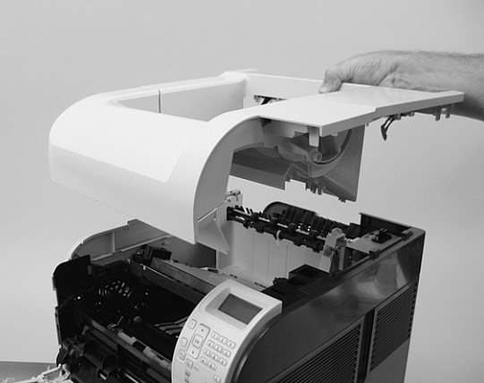
Next, lift the top cover up and off the printer to remove it. There is a free-floating accessory pin (left-rear corner of the top cover) that is not secured to the top cover, make sure it doesn't fall out and get lost in the removal process.
Remove the Right Side Cover
Next, on the right side cover, release three tabs, shown in callout 1 of picture below.
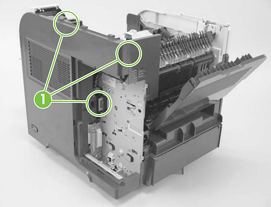
Gently prying near the control panel, carefully separate the right side cover from the printer.
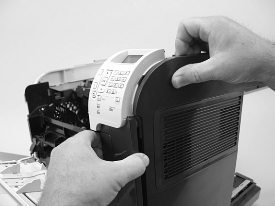
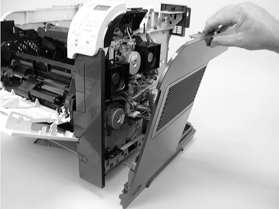
Rotate the top of the cover away from the printer, and then lift the upwards and away to remove it.
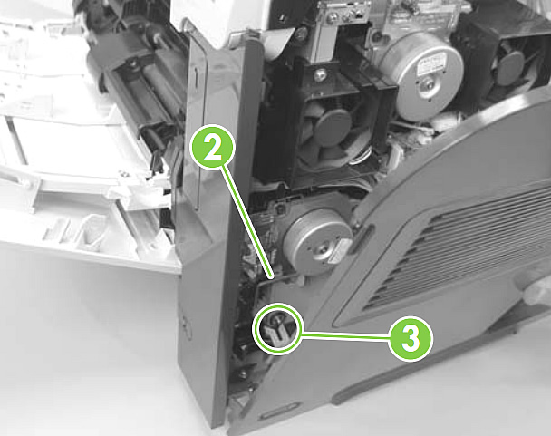
Note: Later, when you are reassembling the printer, as you re-install the right side cover make sure the metal rod (callout 2 in picture below) fits in the notch of the power switch arm (callout 3 in picture below)
Remove the Left Side Cover
Gently pry the front-cover retainers free from the Tray 1 arms.
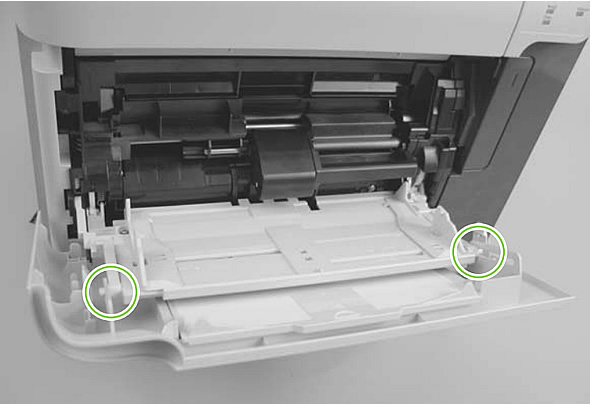
Release the two holding tabs (see callout 3 in picture below).
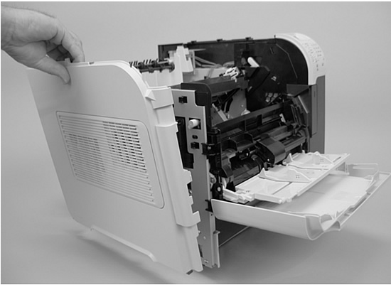
Rotate the top of the cover away from the printer and lift up and away remove it.
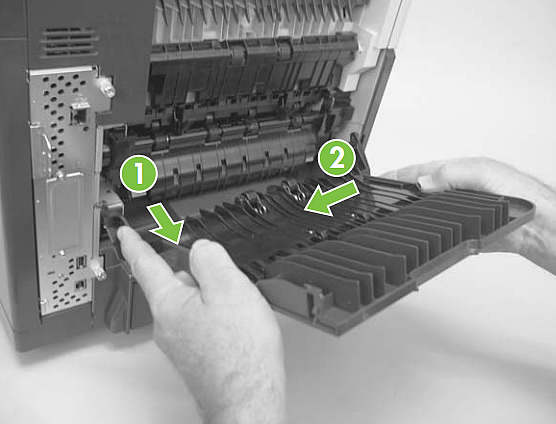
Remove the rear output bin
Open the rear output bin. On the left side of the output bin, near the bottom, is a hinge pin which secures it to the machine. Apply pressure with your finger to gently squeeze the hinge pin out and free from its mounting hole (see picture below).
Gently rotate the left side output bin away from the product until the right hinge pin is also released, then remove the output bin.
That's it for the covers. Proceed to the next step in this process, Removing the Fuser and Power Supply.
Tech Support
Featured Articles